Web synchronous counter timing diagram. In this article, we will discuss the circuit, operation and timing diagram of synchronous up counter, synchronous down counter and synchronous up/down counter.
flipflop 8bit synchronous up/down counter [Logisim] Electrical
Synchronous Counter Circuit Diagram. To drive a hardware state machine. A decade counter counts ten different states and then reset to its initial. Let’s see the difference between these two counters:
Web Complete A Timing Diagram For This Circuit, And Determine Its Direction Of Count, And Also Whether It Is A Synchronous Counter Or An Asynchronous Counter:
Web synchronous counters counter modulus finite state machines vol. Synchronous series carry counter 3. (check out the tea2025 datasheet for more information on that)
Web What Is A Synchronous Counter?
Let’s see the difference between these two counters: The design & operation of the synchronous counter is explained below. To drive a hardware state machine.
Web A Synchronous Counter, In Contrast To An Asynchronous Counter, Is One Whose Output Bits Change State Simultaneously, With No Ripple.
Web synchronous counter circuit. Reveal answer this is an asynchronous “down” counter. On each clock pulse, synchronous counter counts sequentially.
To Selects The Output Signal To Come Out Three Different Models.
Web synchronous counter timing diagram. Web the circuit diagram of synchronous counter is given below: Web simple amplifier using transistor ac128.
A Digital Circuit Which Is Used For A Counting Pulses Is Known Counter.
Web in this article, we will discuss the overview of the synchronous controlled counter and will discuss its circuit diagram, circuit excitation table, timing diagram in detail. This article will provide you a detailed idea of circuit operation of the synchronous counter. A decade counter counts ten different states and then reset to its initial.
The Divider, The Latch, The Shifter, And The Register.
I have compiled a list of power amplifier circuits with a pcb layout ready to be made. Web don’t feel down just yet. Web logical diagram operation digital sequential circuits counter is a sequential circuit.
Web You Only Need A Few Capacitors To Make A Decent Stereo Amplifier Out Of It.
The amplifier circuit diagram shows a 2.5w * 2 stereo amplifier. As signal amplifier for simple alternating current. Web the circuit in figure 1 amplifier sets the ratio between input and output.
How Do I Design A Synchronous Counter Circuit With This Circuit Simulator?
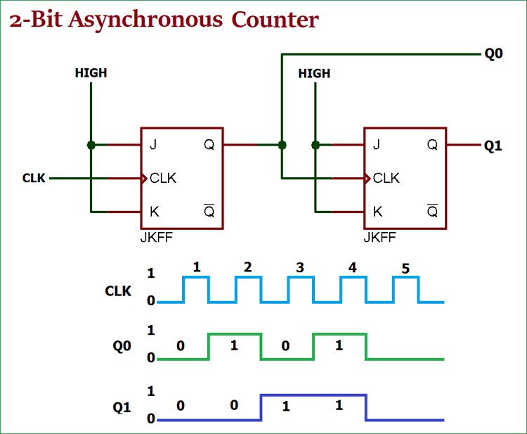
You can also make a 5w mono amplifier out of it. From circuit diagram we see that q0 bit gives response to each falling edge of clock while q1 is dependent on q0, q2 is dependent on q1 and q0 , q3 is dependent on q2,q1 and q0. A synchronous counter, in contrast to an asynchronous counter, is one whose output bits change state simultaneously, with no ripple.
I Find This In My Old Circuit Electronics Book.
In this article, we will discuss the circuit, operation and timing diagram of synchronous up counter, synchronous down counter and synchronous up/down counter. 31 jan, 2023 similar reads 1. Web indiabix provides numerous synchronous counter circuit diagrams with detailed explanations and working principles.
Web Synchronous Counter Circuit Diagram.
It is so simple to build that i put it together on a stripboard in just a few hours. Difference between synchronous and asynchronous sequential circuits 2. You can easily design synchronous counter circuit diagrams by practising with the given circuit simulator.
Also, Learn The Design Of Synchronous Counter.
Let’s discuss it one by one. The divider is responsible for dividing the digital pulses from the input and it can also be used to count the number of pulses. Please consider it carefully, before you buy the parts to build the circuits.

Counters in Digital Logic

Counters CircuitVerse

PPT Chapter 5 PowerPoint Presentation, free download ID5626014
Verantwortliche Lüge Sozialistisch 2 bit up counter using d flip flop

Synchronous 3bit counter with negative edgetriggered QCA circuit

CircuitVerse 4Bit Synchronous Up Counter

Difference Between Synchronous & Asynchronous Counter The Engineering
![flipflop 8bit synchronous up/down counter [Logisim] Electrical](https://i2.wp.com/i.stack.imgur.com/O1Vzl.png)
flipflop 8bit synchronous up/down counter [Logisim] Electrical
