Web strain guge load cells. The four wires coming out from the wheatstone bridge on the load cell are usually:
Strain Gauge Load Cell Inst Tools
Strain Gauge Load Cell Circuit Diagram. In the industry, mostly strain gauge load cells are used. The lumped parameter model ideally assumes that the connecting wires to and from the wheatstone bridge have zero resistance. Strain gauge load cell its working electrical volt.
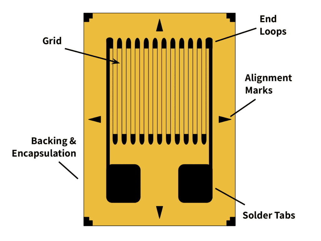
Strain Gauge Diagram The Relationship Between The Change In Resistance Of The Strain Gauge, And The Strain In The Etched Wire Due To An Applied Load, Is Approximately Linear Within The Elastic Limit Of The Wire.
The lumped parameter model ideally assumes that the connecting wires to and from the wheatstone bridge have zero resistance. Web the hx711 load cell amplifier is used to get measurable data out from a load cell and strain gauge. Amplifier circuit works to amplify the output electrical signal of the wheatstone bridge (a few millivolts) to provide a measurable output voltage with accurate data.
And Lastly (Though There Are Many Other Less Common Load Cell Set Ups), There Is A Strain Gauge Load Cell, Which Is A Mechanical Element Of Which The Force Is Being Sensed By The Deformation Of A (Or Several) Strain Gauge (S) On The Element.
It translates the change in force or strain into change in voltage. Web strain gauge load cells. Indicate where the force would be applied:
Web A Strain Gauge Is A Device That Is Used To Measure The Strain That Occurs In An Object.
(please copy the sketch to your answer book) c) discuss the advantages of a wheatstone bridge in this What is a load cell crosby straightpoint uk europe usa. This hookup guide will show you how to get started with this amplifier using some of the various load cells we carry at sparkfun.
Web Strain Gauge Load Cells Are A Type Of Load Cell Where A Strain Gauge Assembly Is Positioned Inside The Load Cell Housing To Convert The Load Acting On Them Into Electrical Signals.
Load cells provide an accurate measurement of compressive and tensile loads. Therefore, when a 10kg load is applied to the load cell, its v out will be 5.0mv (±0.75mv). There are different types of load cells like hydraulic, pneumatic and strain gauge load cells.
This Means That Four Strain Gages Are Interconnected As A Loop Circuit (Load Cell Circuit) And The Measuring Grid Of The Force Being Measured Is.
Strain gauge load cell diagram from scalenet.com. Web these strain gauges are arranged in what is called a wheatstone bridge circuit (see load cell circuit animated diagram). When an external force is applied on an object, due to which there is a deformation occurs in the shape of the object.
Web Strain Guge Load Cells.
What is load cell kubota gravimetric feeder. Web what is a load cell circuit and how they work in force measurement? This relationship is expressed as a ratio known as the gauge factor (\ (g\)).
Load Cells Commonly Function By Utilizing An Internal Strain Gauge That Measures Deflection.
This means that four strain gages are interconnected as a loop circuit and the measuring grid of the force being measured is aligned accordingly. B) indicate where the strain gauges would be placed on a single point load cell and label as in the circuit diagram. Web strain gauge load cell.
The Four Wires Coming Out From The Wheatstone Bridge On The Load Cell Are Usually:
Strain gages are interconnected as a loop circuit and attached to the flexure element which measures the force. Indicate where the strain gauges would be placed on a single point load cell and label as in the circuit diagram. Web draw a circuit diagram for a load cell using 4 strain gauges in a wheatstone bridge.
Strain Gauge Load Cell Its Working Electrical Volt.
Web strain gauge load cell is an application of wire type bonded strain gauge. A load cell is a force measurement device. Web as the distance between the strain gauge and the three other resistances in the bridge circuit may be substantial, wire resistance has a significant impact on the operation of the circuit.
Web The Load Cell's Wheatstone Bridge Strain Gauge Schematic.
These cells convert load or force (p) into electrical output, which is provided by the strain gauges. The device is still being used in many electronic circuits mainly as the principle sensing element for sensors like torque sensors, pressure sensors, load cells and so on. Web these strain gauges are arranged in what is called a wheatstone bridge circuit (see animated diagram).
Strain Gauges Are Arranged In What Is Called A Wheatstone Bridge Circuit (Aka Load Cell Amplifier Circuit).
In the industry, mostly strain gauge load cells are used. Web in general, each load cell has four strain gauges that are hooked up in a wheatstone bridge formation as shown above. Web load cells full bridge strain gauges monodaq.
In A Load Cell, A Transducer Is Used To Convert Force Into A Proportional Electrical Signal.
In order to measure strain, these types of load cells must be connected to an electric circuit that is capable of measuring the minute changes in resistance. Half bridge strain gauge circuit scientific diagram Web a) draw a circuit diagram for a load cell using 4 strain gauges in a wheatstone bridge.
For This Project I'll Be Applying 5.0Vdc As The Excitation;
Strain gauge amplifier with digital and analog output load cell. A load cell is an electromechanical transducer that converts load acting on it into an analog electrical signal. To illustrate the effects of wire resistance, i’ll show the same schematic diagram, but add two resistor symbols in series with the strain gauge to.
Working Principle & Diagram October 22, 2020 By Electrical4U What Is A Strain Gauge A Strain Gauge Is A Resistor Used To Measure Strain On An Object.
The device was invented in the year 1938 by edward e.

Strain Gauge Load Cell 4 Wires 10Kg ID 4542 3.95 Adafruit

Load Cell Load Sensors Quality Scales Unlimited

Strain Gauge Working Principle your electrical guide

Strain gauge load cell 50 kN

Strain Gauge Working Principle with Animation Instrumentatio Tools

Learn About Strain Gauge Type Load Cells Tacuna Systems

Strain Gauge Load Cell Inst Tools
Learn About Strain Gauge Type Load Cells Tacuna Systems
