In order to analyze any electric circuit, it is necessary to understand the following three cases, 1) ag. Introduction to single phase ac circuit:
The post explains an interesting single phase AC to 3 phase AC circuit
Single Phase Ac Circuit Diagram. 2 understand and use the concepts of reactance and impedance to analyse simple a.c. Impedance, phase relations, resonance and rms quantities are shown on this resource page from physclips: Alternating current electricity time and phasor animations are used to explain alternating current (ac) circuits.
By Using The Diagram, A Technician Can Quickly Find The Right Wire And Terminal Connections And Make Sure All Of The Components Are Installed Correctly And Are Operating Correctly.
Web 1 draw the relevant phasor diagrams and waveform diagrams of voltage and current, for pure resistance, inductance and capacitance. The sinusoidal variable value can be represented by a rotating line called the phasor. Direct current (dc) and alternating current (ac) are the two types of electricity.
In A Dc Circuit The Relationship Between The Applied Voltage V And Current.
If the load resistor’s power dissipation were substantial, we might call this a “power circuit” or “power system” instead of regarding it as just a regular circuit. In this article, we will discuss both type of voltage controller in detail and illustrate the working with relevant circuit diagram and waveforms. Depicted above, is a very simple ac circuit.
Register To Download Premium Content!
Single phase half wave and single phase full wave. Two loops are embedded in the control: Working principle of single phase ac voltage controller:
Impedance, Phase Relations, Resonance And Rms Quantities Are Shown On This Resource Page From Physclips:
Introduction to single phase ac circuit: Dc is the unidirectional flow of electric charge. The simplified version of a ac generator is discussed here.
Dc Circuit And Ac Circuit Show The Structure Of The Respective Circuit Systems.
Web there are two types of single phase ac voltage controller: The main components of ac circuits are resistors, capacitors, and inductors. 2 understand and use the concepts of reactance and impedance to analyse simple a.c.
Web Phasor Diagrams Present A Graphical Representation, Plotted On A Coordinate System, Of The Phase Relationship Between The Voltages And Currents Within Passive Components Or A Whole Circuit.
Web single phase power system schematic diagram shows little about the wiring of a practical power circuit. Posted on december 30th 2020. Web single phase ac circuit (with diagram) | electrical engineering 1.
Find The Voltage Across Each Element And Total Current Supplied By The Supply And Draw The Phasor Diagram For The Circuit.
Web electrical tutorial about ac inductance and the properties of ac inductance including inductive reactance in a single phase ac circuit. Such representations are called phasor diagrams. The phasor diagram for \(i_r(t)\) is shown in figure \(\pageindex{3a}\), with the current on the vertical axis.
How, Exactly, Do Overload Heaters Protect An Electric Motor Against “Burnout” From Overcurrent Conditions?
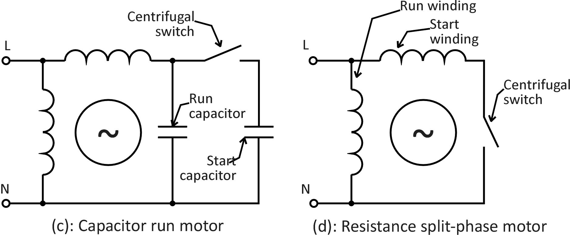
Web boost circuit i s |v | pfc d pwm generator control |v s| i l v o fig. The output voltage of boost circuit. Web a single phase ac motor control circuit diagram is an invaluable tool for any technician working on this type of motor.
Inner Loop For Inductor Current Control And Outer Loop For Output Voltage Control.
Depending upon the number of phases of the ac output, there are several types of inverters. Web graphical representations of the phase relationships between current and voltage are often useful in the analysis of ac circuits. Circuits 7.1 introduction the resistance, inductance and capacitance are three basic elements of any electrical network.
Alternating Current Electricity Time And Phasor Animations Are Used To Explain Alternating Current (Ac) Circuits.
Vectors have both magnitude as well as direction. In order to analyze any electric circuit, it is necessary to understand the following three cases, 1) ag. Web typically in the analysis of ac circuits, the voltage waveform of the power supply is used as a reference for phase, that voltage stated as “xxx volts at 0 degrees.” any other ac voltage or current in that circuit will have its phase shift.
A Power Inverter, Or Inverter, Is An Electronic Device Or Circuitry That Changes Direct Current (Dc) Into Alternating Current (Ac).
The pfc control diagram of the boost circuit is shown in fig. Web of 27 single phase a.c.

The post explains an interesting single phase AC to 3 phase AC circuit

220V Single Phase Motor Wiring Diagram Cadician's Blog
Wiring Diagram For 230V Single Phase Motor Collection Wiring

Single Phase Forward Reverse Motor Wiring Diagram 3 779x1024 On Single

Single phase AC circuit

Solved Fig. 1. Singlephase ac circuit 52 j10Ω 100sin3771+9)

Types of AC Generators Single Phase and Three Phase AC Generator

Closed Loop Single Phase AC Motor Speed Controller Circuit
